A dramatic moment at the Exposition was the unveiling, by Walt Disney, of a model of the Monsanto Plastics House (AR, Jan. '56, p. 205). Designed by architect Marvin Goody as part of a plastics research project under the direction of Richard Hamilton and sponsored by Monsanto at M.I.T., the "House of Tomorrow" will be built at Disneyland in Anaheim, Calif. Construction will start late this year. Following ia a structural evaluation of the house which was prepared by Albert G. H. Dietz, F.J. McGarry and F.J. Heger of M.I.T.
Design of a "House of Tomorrow," embodying the maximum use of plastic, has been undertaken to see how plastic can most advantageously be employed in a house designed from the outset to utilize plastics as plastics rather than as substitute for other materials. Architectural and engineering design have been closely related from the beginning to attain this objective. A major consideration is the fact that plastics can be formed rather readily into large compound curves, that such curves are structurally efficient and that structure and enclosure can be combined to allow plastics to perform a double function, thereby making the material perform to its utmost.
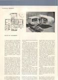
The house has a cross-shaped plan consisting of a 16-ft-square central area and four 16-ft-square wings. The central area is supported by four columns resting on a foundation. The wings are cantilevered from the central section.
To meet shipping restrictions, the roof and floor are made of 8-fl by 16-ft molded reinforced plastics sections. Both are hollow shell whose exterior portions are identical in shape and are therefore all made on the same mold. Sixteen such sections are required. The floor itself forms the inner portion of the floor shell, and is a sandwich with reinforced plastics face and either a honeycomb or foamed polyisocyanate core. Floor and roof shells are made deep enough to develop the necessary stiffness. The ceiling or inner portion of the roof shell is curved for best lighting a well as for structural efficiency in resisting compressive buckling stresses.
In the central section direct tensile and compressive stresses have to be transmitted from wing to wing, and bending stresses must also be resisted because of floor loading. Two sandwiches form the structure of the central section. An upper one carries floor loads in bending plus direct tensile stresses from the wing. A lower one resists the compressive thrusts from the wings. Similar structural sandwiches in the roof of the central section carry the tensile and compressive thrust from the roof shells. A series of spandrels and intermediate ribs helps to support the load and to provide stiffnes. The load analysis required a study of dead loads alone, live loads over-all, live loads distributed over individual wings, wind loads uniform on entire house, wind loads unequally distributed because of difference in exposure, and earthquake.
Design throughout was concerned more with stiffness than with strength. If deflections were held within generally accepted bounds for building, stresses were usually well within allowable limits. By tying wings and central sections together, and by connecting the outboard ends of roof and floor shells, maximum resistance to deflection and torsion was obtained.
Columns, which carry only direct downward or uplift loads and can therefore be made slender, are sunk down to a reinforced concrete foundation slab and stiffened in the foundation area by large gussets made integral with the floor spandrels.